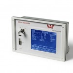
The S-Keeper 7™ is in strict compliance with the MARPOL Directive requirements but its Mission is even more important.
Since 1974 TECNOVA Group has delivered thousands of devices, such as meters, oil in water analysers, viscometers, shaft monitoring etc., to improve the management of cruising ships, cargoes, chemical tankers, RO-ROs,etc.
With the benefit of our extensive experience S-Keeper 7™ was engineered to be a smart hub able to aggregate several outputs from the instrumentation offering a unique view of ship performance.
Don’t miss the opportunity to turn the cost of Directive compliance into an investment: S-Keeper 7™ offers the chance to retrofit your vessel in the easiest way, slashing the fuel bill and minimizing air pollution.
Here are the suggested companions to S-Keeper 7™:
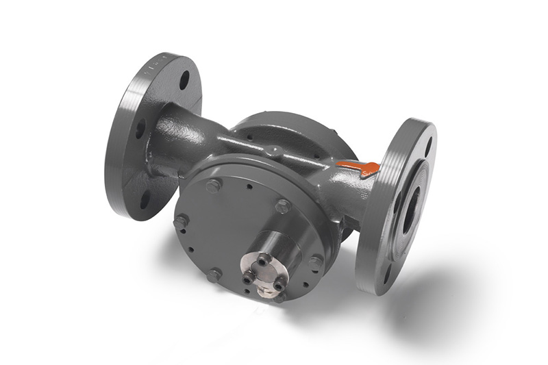
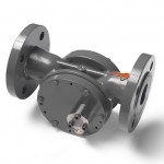
Positive Displacement Meters: These liquid flow meters take accurate volumetric measurements for a wide range of liquids, from low-density LPG to fuel oil. They are ruggedness itself. Every single drop of oil is metered and counted, day by day, for dozen of years of uninterrupted service. They are not affected by ship rolling or vibrations, unlike other technology, and they are the first choice for thousands of ships. If you have had a poor experience with PD meters on board you have not installed ours.
PD Meters & Viscosity analysis to increase Ship Efficiency
Positive displacement flowmeters operate on the sliding vane principle. The meter consists of a specially shaped housing in which a rotor can rotate freely. Two pairs of vanes are placed into four slots in the rotor. Each pair is positioned by a rod and can move in and out of the rotor. The radial movement of the vanes is guided by the special inner shape of the housing. This patented construction provides a constant seal between the inlet and the outlet of the meter. The incoming liquid forces the rotor to rotate. The rotation of the rotor is transferred via a magnetic coupling to a read out device. This can be a counter in any engineering unit you wish or a pulse transmitter for remote read out, flow data processing or connection to a process computer.
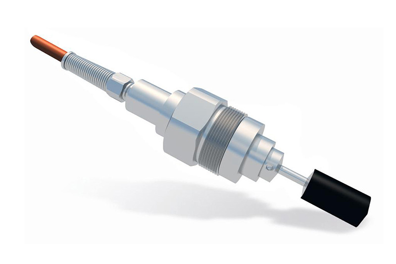
Shaft Power Torque & Thrust Meters: Using the T-Sense® or the TT-Sense® for measuring thrust and torque results gives you an insight into your propeller efficiency, vessel pitch optimization and hull resistance.
T-Sense® & TT-Sense® – Shaft Power Torque & Thrust Measurement – Overview
The use of a T-Sense® torque measuring system means efficiency improvement, overload protection and prevention of breakdown costs. For example, its application in the shipping industry has led to savings up to 5% on fuel costs. The system is based on extremely accurate optical sensor technology and can be mounted around shafts in power transmission systems. T-Sense® torque measuring systems are maintenance-free as a result of noncontact power and signal transmission. The upcoming new IMO regulations (SEEMP) inspired development of the next step in this successful line of sensors: the TT-Sense® Torque & Thrust measurement provides you with precise information on propeller efficiency related to consumed energy. By giving instantaneous read-out of real thrust, torque, speed and power, the effects of operational changes are monitored. Because these effects are measured, you can use your propulsion installation in the most efficient way. This will considerably reduce your fuel costs, and beside that, malfunctions in the propulsion system will be discovered as early as possible, both of these being primary cost drivers.
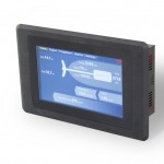
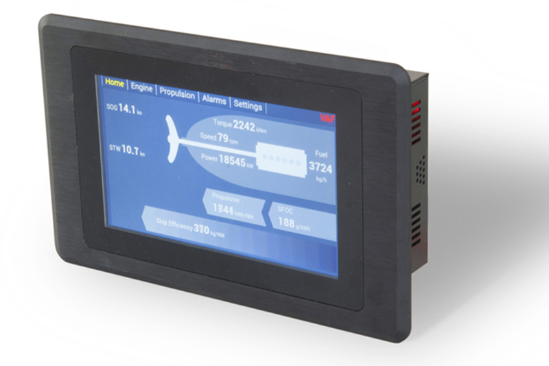 PEM Propulsion Efficiency Monitor: The PEM4 Propulsion Efficiency Monitoring system is a microprocessor based instrument for use with the T-Sense®, TT-Sense® and fuel Flowmeters.
PEM2 Propulsion Efficiency Monitor by VAF Instruments
Functions which can be performed with the PEM4 system are:
- Measurement and display of the torque, thrust, shaft speed and power.
- Calculation of the average shaft power, shaft speed and torque during the last 1, 4 and 24 hours.
- Calculation of the total energy, total revolutions and total CO2 emissions including reset.
- Calculation of the fuel consumption in kg per nautical mile, fuel consumption in kg per hour, fuel consumption in gram per kWh (Specific Fuel Oil Consumption – SFOC), average fuel consumption per nautical mile, fuel temperature compensation and calculation of the total mass per fuel type per consumer including reset.
- Calculation of thrust, thrust power quotient when a TT-Sense® sensor is installed.
- Display of parameters, engine load diagram and power/speed diagram.
The T-Sense® provides torque, shaft speed and power as input for the PEM4 system while the TT-Sense® additionally provides thrust measurements as input. The PEM4 system is supplied with a robust SPU3 Signal Processing Unit, which can be connected to a large number of extra inputs such as flowmeters, GPS, speed log, or one additional T-Sense® or TT-Sense® in case of twin screw vessels. In detail the SPU3 can manage a maximum of 12 flow meter inputs in combination with PT100 temperature inputs related to a maximum of 6 consumers. The SPU3 converts all these input signals to one RJ45 Ethernet signal for monitoring purposes. A RS485 Modbus signal is available for connection to an external system such as Alarm and Monitoring System (AMS) or to connect a separate PC running the optional PEM4 datalogger software.
The SPU3 can be installed in the vicinity of the flow meter(s) and/or booster unit or in the engine control room (ECR). The PEM4 touch screen can be installed in a control cabinet or control panel in the ECR and/or on the bridge.
Besides checking the status of the torque measurement system and/or flowmeters the PEM4 system also checks itself continuously for program and configuration data integrity, normal program flow and power supply conditions. All alarm messages will be logged on a dedicated alarm screen.
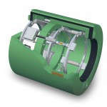
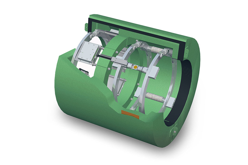
 Viscosity in line analyzers: The patented ViscoSense® system is used for continuous in-line measurement and control of fuel oil viscosity & temperature for diesel engines on ships.
ViscoSense®2 Viscometer and Viscosity Control System
A large variation in the quality and composition of fuel oil, makes the behavior of the fuel oil difficult to predict at higher temperatures. An optimal viscosity is required for the best possible atomization of HFO in the engine, so the fuel will be burnt completely without leaving deposits. The measurement and control of the viscosity ensures improved combustion efficiency, preventing engine damage and reducing the cost of maintenance. Viscosity control contributes to a green environment. This patented measuring principle is based on the torsional vibration of a pendulum in liquid. The measured damping of this piezo-driven vibration is directly related to the viscosity. A built-in temperature sensor is used to measure the temperature at the same location where viscosity is measured. ViscoSense®2 is able to measure inline the actual dynamic viscosity of a large range of liquids. Due to the operating principle based on a torsional vibration, the measurement is insensitive to unwanted external influences. Flow velocity, flow direction and pulsations have no effect on the sensor operation. The robust built sensor is designed to operate under the most difficult conditions in which faultless and stable viscosity measurement is required.
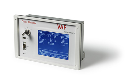 Oil Discharge Monitoring & Control Systems: For the continuous on-line monitoring of discharge water during de-ballasting operations, the Oilcon® Mark 6 is a proven solution known worldwide.
The measurement technique used in the Oilcon® is based on scattered light. In accordance with IMO Resolution MEPC.108(49), the Mark 6 Oilcon® is able to discriminate between oil and other contaminants such as mud, rust or entrained air. A sample of discharge water passes through a detector cell while light enters and leaves the measurement area of the cell. The sample flow is at right angles to the optical path. When no particles or oil droplets are present in the water, light can pass straight through the cell (Direct beam). When oil is present in the form of a homogeneous mixture, light is scattered at different angles (Scatter beam). The intensity of scattered light at a specific angle depends on the density of oil droplets and upon their particle size relative to the wavelength of radiation. The intensity of light of the direct beam decreases logarithmically with increasing oil concentration, while the scatter beam increases linearly but passes through a maximum before decreasing logarithmically.
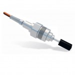
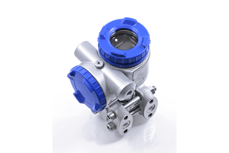 Marine Certified Pressure Transmitters: the FCX-AII V5 Smart Hart® family of fully marine certified transmitters offer measuring ranges from 10 mmWC and 500 bar and are available for differential, gauge and absolute pressure.
Extensive experience in silicon chip manufacture enabled the engineering of a unique micro capacitance silicon sensor as the centerpiece of FCX-AII transmitters. To minimize static pressure and overpressure temperature effects, this silicon sensor is assembled floating in the measuring cell neck. As a measuring diaphragm material, the sensor uses a single crystal silicon that has minimal hysteresis and fatigue which enhances the transmitter’s characteristics, improving its long-term “zero” stability and reliability.
With 0.065% Standard accuracy or even better with 0.04% Improved accuracy , a 100:1 rangeability and the various materials available for wetted parts (Tantalum, Monel, Hastelloy-C or PVDF) our transmitters can be used in various applications in industry fields such as marine, petrochemistry, chemistry, energy, iron industry, food industry and water treatment.
The FCX-AII V5 transmitter can be fitted with an optional local analogue or digital indicator. The digital indicator is based on LCD technology and shows the information on 2 lines each of 6 digits and also includes 3 switches. The indicator can be used to show the output signal in engineering units as a percentage or as a current in mA (this is useful for flow indication on a differential pressure transmitter).
In conformance with the recommendations of NAMUR NE 43, the output of the transmitter can be driven to a specific value should the transmitter experience an internal failure. The standard output signal limits are 3.2 to 22.5 mA. In the event of a transmitter failure, the burnout direction can be down scaled (3.2 to 4 mA) or scaled up (20 to 22.5 mA), being programmable.
The calibration parameters are saved in the transmitter. At any time it is possible to reset to the factory calibration of the transmitter. Min and max temperatures are stored in the transmitter memory. It is always possible to view the values on a specific menu on the screen of the hand held communicator.
All the adjustment functions of the transmitter can be locked by a password (the external adjusting screw is also locked).
What is Marpol? Are you looking for “Marpol definition”, “Marpol meaning”, “Marpol regulations”, “Marpol directives”, “Marpol Annex VI” and so on? Go to this page.