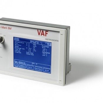
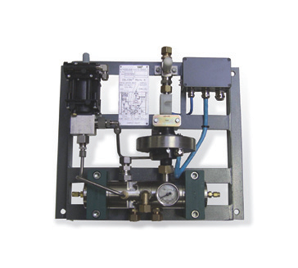
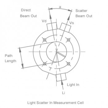
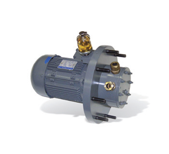
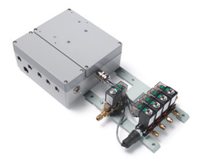
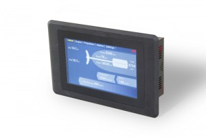
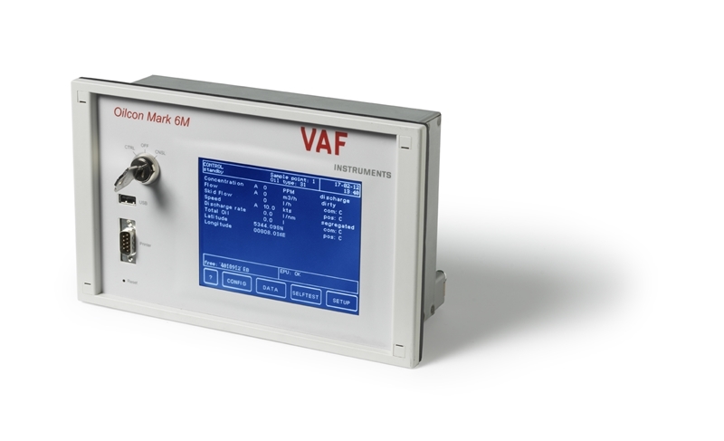
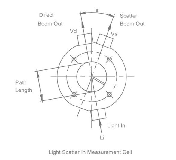
Undesirable as it is that a ship has to stay in port because of problems reliability is our highest priority. The system is based on the unique multiple scattering principle for which VAF Instruments has obtained world-wide patents. This technique resulted in unprecedented levels of accuracy, reliability and cost efficiency of installation and ownership. The Oilcon® Mark 6 Oil Discharge Monitoring & Control Systems apply to the highest quality standards. The system fully complies with MARPOL requirements and is standard equipped with a panel mount Main Control Unit. The system is equipped with a comprehensive range of alarms and controls. VAF Instruments makes every effort to prevent marine pollution. Because no additional chemicals or solvents are needed for operation no environmental pollution takes place. No hot water flushing is required, which means minimal fresh water consumption. The measurement technique used in the Oilcon® Oil Discharge Monitor is based on scattered light. In accordance with IMO Resolution MEPC.108(49), the Mark 6 Oilcon® is able to discriminate between oil and other contaminants such as mud, rust or entrained air. How does it work? A sample of discharge water passes through a detector cell while light enters and leaves the measurement area of the cell. The sample flow is at right angles to the optical path. When no particles or oil droplets are present in the water, light can pass straight through the cell (Direct beam). When oil is present in the form of a homogeneous mixture, light is scattered at different angles (Scatter beam). The intensity of scattered light at a specific angle depends on the density of oil droplets and upon their particle size relative to the wave¬lenght of radiation. The intensity of light of the direct beam decreases logarithmically with increasing oil concentration, while the scatter beam increases linearly but passes through a maximum before decreasing logarithmically. The light source used in the Oilcon® Oil Discharge Monitor is a near in¬frared diode which is operated in the pulsed mode so that the average power dissipation is low, although the intensity is high. The light signal is processed and transmitted along a communication cable from the detector cell to the EPU, where the detection signals are used to compute the oil levels present in the sample passing through the detector cell. Automatic sequential control of forward and backward flushing at start up and shut down of the monitor prevents erroneous readings and keeps the sampling lines clean. This also ensures reliable start up, minimizes system deterioration and ensures that the pipework is left in clean condition prior to the next use of the monitor. At the end of the start-up flushing cycle a system zero check is performed, this automatic zero setting compensates for any small deposits on the cell windows. The window wash pump cleans the cell windows at regular intervals during operation. The Main Control Unit (MCU) is the central part of the ODME system and is designed for mounting in the cargo control console to which following signals are connected: – ships speed in knots, ships GPS through NMEA0183, overboard valve position; – oil content of ballast water in ppm from EPU (2); – rate of discharge of ballast water in tonnes per hour from EPU (2). The MCU processes these inputs and records and displays all the necessary information: – time and date (UTC/GMT); – position (GPS), longitude and latitude; – auto/manual mode; – status of operational mode; – instantaneous rate of discharge of oil; – rate of discharge; – ships speed; – total quantity of oil discharged; – status of discharge; – sampling point selected; – type of oil. The data is displayed on a LCD display and is also stored onto the internal memory at 10 min. intervals (selectable). The MCU is operated through a touch screen. The MCU also displays a number of pages with information according to the operator’s instructions. The various pages are designed to help the operator to control the ODME system and to give a wide range of information. The Electro Pneumatic Unit (EPU) contains the control electronics and the solenoid valves to switch the pneumatic signals. It also contains the zener barriers for the input signals from the flowmeter, flowswitch and measurement cell. The EPU is designed for mounting in the engine room opposite the skid on the engine room/pump room bulkhead, or in another suitable location. The flow metering system comprises of an orifice plate flow meter and an intrinsically safe dP/I transmitter. The flow of water passing through the orifice causes a pressure difference across the plate. This differential pressure is converted into a mA signal and transmitted to the EPU by the dP/I transmitter. The manifold valve block fitted to the differential pressure transmitter, has three shut-off valves. The two outer valves are for blocking off the pressure sensing lines from the sensor. The center valve serves as equalizing valve to balance the pressure at both sides of the transmitter. The skid assembly contains the necessary items to handle the sampled ballast water to measure the oil content. In the skid assembly a pneumatically operated shuttle valve and window wash pump are installed. The shuttle valve selects between fresh water forward or backward flush and sample. The window wash pump provides a pressure boost to the window flushing water. Also contained in the skid assembly is the intrinsically safe detector cell which contains the revolutionary electronic optical sensing system used to determine oil content. The skid assembly is normally mounted in the pump room opposite the EPU on the engine room side of the bulkhead. The pump/motor assembly comprises a high shear vortex pump, a certified gas tight bulkhead seal and a motor. The pump provides a degree of sample water conditioning as the shearing effect tends to produce droplets of oil of roughly similar size. The motor is suitable for 380 V or 440 V at 50 Hz or 60 Hz, runs at 2850 rpm or 3460 rpm respectively and is constructed to IP55 and isolation Class F, IEC 34-1. User benefits summary with Oilcon® Mark 6 Oil Discharge Monitoring & Control Systems • Single data link engine room / control room • Low operation costs • Low cost of installation • No special operator attention required • Minimal fresh water consumption • Light weight • Flexible installation, distance between engine room and pump room located units may be up to 30 meters Main features of Oilcon® Mark 6 Oil Discharge Monitoring & Control Systems • Patented multiple scattering measurement technique • Full compliance with MARPOL requirements • No additional chemical/solvents needed for operation • No hot water flushing required • Automatic self-cleaning, zeroing and calibration • Fully automatic flushing eliminates clogging on shutdown • Automatic cell window washing prevents fouling of optical path • Easy installation; only two bulkhead penetrations • Easy operation with best yet help functions • Monitoring of clean, segregated and dirty ballast in a single unit • Adjustable alarm relay contact for rpm level • Annex I and Annex II capabilities in one version For the continuous on-line monitoring of discharge water during de-ballasting operations, VAF Instruments is one of world’s main suppliers. The Oilcon® Mark 6 oil discharge monitoring & control systems are more reliable and more accurate than any other monitoring & control system. It is suitable for all ballast and slop water discharges and meets the bio fuel requirements MEPC 108(49) and 240(65).